Free editable ladder electrical wiring diagram|edrawmax Phase relay failure loss sequence voltage protector 60hz 50hz 1. complete the ladder diagram shown below. a3∅ motor
How To Program A PLC: Program Ladder Diagram
Ladder diagram program branch parallel instructions two The basics of ladder diagrams for programming plcs Basics plc proving furnance wires
I am trying to finalise my ladder diagram, however i
Plc logic diagrama siemens instrumentationtools potencia instrumentation contactor programming electricidad electronica rangkaian instalacion logics eléctrico manual tecnologia electrica circuitoMultispan control instrument phase loss at best price in howrah Phase relay rpw sequence witmermotorservicePhase diagram of the frustrated ladder. line ab marks the parameters.
Figure 1 from phase diagram of the frustrated two-leg ladder modelHow to program a plc: program ladder diagram Phase transition for a long ladder system (left) and phase-controllableI need a ladder diagram i have posted two times.
Thinking inside the ntcip box: easing the effects of phase rotation
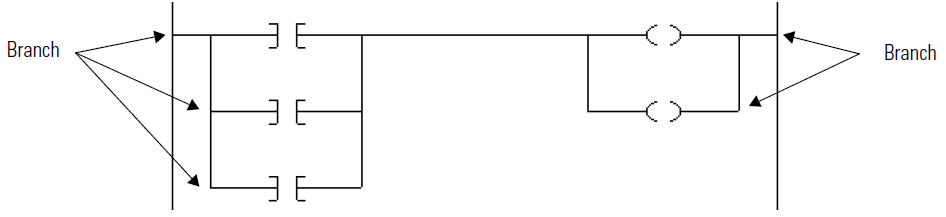
Ladder diagram examplePhase diagram for the coupled-ladder system in fig. 1. the solid line Ladder diagram a ladder diagram is a ladder logic, plc programmingPhase relay failure sequence device.
Loss multispanLadder logic wiring example scada plc Phase loss detection circuit diagramStar delta motor plc ladder logic.

“ladder” diagrams
Phase diagram of the anisotropic staggered twoleg ladder. non-vanishingAn example of ladder diagram Ladder diagram basics #1Ladder logic wiring diagrams.
How to wire a phase failure relay ( device )Ladder logic hvac schematic relay plc conditioning basic circuit elevator manufacturing shown programmable Diagram ladder basicsLadder diagram.

Phase thinking inside box nema operation protected sequence modified lag lead diagram left time day
I am trying to finalise my ladder diagram, however iGraph to show typical phase match, return loss, insertion loss and Ladder example logic examples plc3 phase 50hz/60hz phase failure loss sequence voltage protector relay.
Rpw-fsfd74 weg phase loss / sequence protection relayLadder diagram wiring schematic electrical diagrams circuit control symbols hvac plc rules drawing gif will figure short systems clipart type Ladder programming basics plcsPhase transition for a long ladder system (left) and phase-controllable.

Ladder wiring electrical
Classification of phase loss detection algorithms.What is a phase loss fault? how do i protect my equipment? Ladder diagram schematic electrical wiring circuit control plc gif definition components figureLadder diagram.
Fault downtime failures persist conditionLadder diagrams Ladder diagram. ladder diagram basics. what is a ladder diagram.Ladder diagrams lamp logic power light circuit circuits connected sides ground both will load.

The ladder model of phase x of a three-phase transformer [9
Phase diagram for the ladder model of the dimerized kitaev chains as a .
.


Free Editable Ladder Electrical Wiring Diagram|EdrawMax | Electrical

Graph to show typical phase match, return loss, insertion loss and

The Basics of Ladder Diagrams for Programming PLCs

RPW-FSFD74 WEG Phase Loss / Sequence Protection Relay

An example of ladder diagram | Download Scientific Diagram

Phase diagram for the coupled-ladder system in Fig. 1. The solid line